

User Configuration - Control Tuning

click on either display for larger graphic
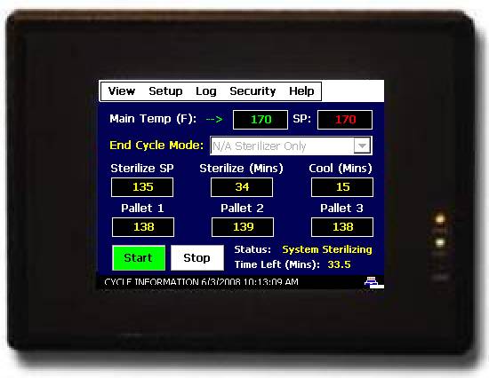
The “Setup” menu from FDC-2010-K5C main menu structure provides access to the setup section of the FDC-2010-K5C.
![]()

![]()
The Setup Screen “Setup” menu provides the following functions:
Kiln System Settings: Settings for web server/IP address display.
Fan Direction Setup: Settings for fan direction and dwell timing.
Temperature Alarm Settings: Settings for Temperature alarms.
PC Remote/Local Mode: Settings PC control or Orion local control of schedules, setpoints, etc.
Schedule Recovery: Settings Schedule recovery during power loss.
Control Tuning: Loop tuning for temp, vents and spray.
IO Monitor: IO monitor for system inputs.
Analog Input Alarm Delays: Delay settings for each input before probe failure alarm occurs.
Offline System Setup: Access to offline system settings (data/time etc.)
The Setup Screen “Views” menu returns the user to the main kiln view:
The OEM configuration of the FDC-2010-K5C as a Kiln only, Pallet Heat-Treat only or as a Combination Kiln & Pallet Heat-Treat configuration will determine the Settings menu; above is for Kiln or Combination unit while directly below is for a Pallet Heat-Treat only configuration.

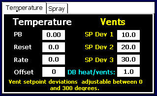

The Control tuning screen allows the user to adjust the Proportional, Integral [Reset], Derivative [Rate], known as PID parameters, when PID control is configured for Heat, Spray and/or Analog Vent control. For more detailed information refer to the FDC-2010-K5C manual.
Whether Control Tuning is used is dependent upon FDC-2010-K5C configuration. Refer to documentation provided by the Kiln Manufacturer as to the FDC-2010-K5C configuration and/or request a copy of the “FDC-2010-K5C_Kiln_Heat-Treat_Config_Manual_Rev_2.1.doc”.
Control tuning values for temperature, vents and spray are displayed. The Kiln control can be equipped and configured to control each of these process variables using relay or analog outputs.
Relay Output for Temperature and Vent Control: When configured for relay output as On/Off control, the PID values for temperature and spray should set at values of "0".
Relay Output(s) for Vent Control: When configured with one or more relay outputs for the Vent setpoints (1 through 3) can be adjusted as a deviation from wet bulb value. As the wet bulb temperature increase above each of the 3 setpoints, relay outputs for vent 1, 2 and 3 will be energized.
Analog Outputs for Temperature, Spray and/or Vents: When configured for analog 4-20mA output (non-relay control), PID tuning values for temperature, vents and spray can be adjusted.
If variable vent control is configured in the system, the setpoint deviations for relay vent control [as shown in graphic below] will dynamically change to PID settings for vents. When Vent control is configured for relay operation as in the graphic shown above, this display provides setting of deviation setpoint values for the vents [Vent deviation values are referenced to either the Dry or Wet bulb setpoint as configured by the Kiln OEM.] When using on/off control for heat and spray, PID values should be left at 0 so the relay outputs do not proportion based on the entered PID settings.
Deadband applies to on/off control and is the difference in degrees C or F between when the relay opens & closes around setpoint and may be set from 0 to 50 degrees C or F.
Offset is applicable to both PID and on/off control. With PID Offset is a "manual" reset of the proportional band around setpoint. When the proportional band is set to zero (0) the control output is on/off. With on/off control Offset shifts the control point the plus or minus value configured in the Offset field. Offset for Proportional or on/off control may be set + / - 80 degrees C or F. [Note Offset Field is not shown in above Graphic - it is located lower left below Rate.]
Proportional Control Tuning and On/Off Settings
1) Control Tuning [PID] applies to proportional control outputs and involves adjusting the following parameters:
Proportional Band is abbreviated as PB
Integral is abbreviated as Reset.
Derivative is abbreviated as Rate.
Note: Control Tuning and/or proportional control are typically abbreviated as “PID Control.”
Offset or Manual Reset shifts proportional band around setpoint - refer to section 2.1 below.
Deadband [also known as Hysteresis] – applies to On/Off Control – refer to section 3.2 below.
1.1) Proportional Band
Proportional Band: Adjustable 0.00% to 100.00% of Span.
Too much or little proportional band will result in poor control performance – see “P Action” graphic on next page.
Note: Proportional Band Setting of 0.00% = on/off control – see section 3.
Analog Input Type: Range Values Range Span
RTD Pt -100.0 to 500.0C and -148.0 to 932.0F 600C and 1,080F
Example: proportional band of 10% for an RTD C input = 60 degree C proportional band.
1.2) Integral / Reset
Reset: Adjustable in seconds [0.0 to 2000.0 seconds].
0 seconds = no reset
The higher the value, the longer the reset time for proportional band offset by reset circuit [an integration factor].
Too much or little rate will result in poor control performance – see “I Action” graphic on next page.
1.3) Derivative / Rate
Rate: Adjustable in seconds. (0.0 to 300.0 seconds)
0 seconds = no rate.
The higher the rate value the faster the process will respond to upset changes.
Too much or little rate will result in poor control performance – see “D Action” graphic on next page.
1.4) Offset / Manual Reset
Offset: Adjustable plus/minus 50.0degrees.
This adjustment “shifts” the proportional band to a set % output around the setpoint value.
1.5) Cycle Time
Cycle Time: Adjustable 0 to 300 seconds.
Cycle time is the complete duty cycle of the relay output On/Off time. Default is set at 10 seconds.
Cycle Time Example: A cycle time of 10 seconds would perform when controlling at 50% output as 5 seconds “on” and 5 seconds “off” duty cycle.
Typically shorter cycle time provides better control, however relay life is accelerated at shorter cycle times.
2.1) Proportional only Control - Reset & Rate both set to 0.00
FDC-2010-K5C Kiln Control configured for Proportional output only [Reset & Rate set to 0.0] the Proportional Band is “one-sided”; i.e. as temperature increases the percent output will decrease to 0% at setpoint. Without “Reset” or “Offset” the process value will likely settle at a value below setpoint.
“Offset” manually shifts the proportional band [% output] around setpoint with the intended result that process value equals setpoint. Utilizing Proportional only control without Reset or Rate but with Offset is a good strategy if the load conditions are the same through all process control conditions; typical conditions for hard wood dry kilns.
When tuning with Proportional Band only [Reset & Rate set to 0], enter a proportional band value that controls the process at a stable process value without oscillation. Prior to using Offset this stable process value will likely not be equal to setpoint. Once process value has maintained a steady state OFFSET may be adjusted to shift the proportional band to allow process value to equal setpoint.
2.2) Proportional Control with Reset and Rate – full PID control
For process control systems that have various load conditions utilizing all three PID parameters may help to maintain process variable at the setpoint values without operator action.
Reset [Integral] will automatically move the PB to the required % output to maintain process value. It is best to allow at least 20+ minutes between adjustments made to any PID setting.
Rate [Derivative] should only be used if an adjustment to output is required for fast changing systems.


3) On/Off Control Offset and Deadband
When the Proportional Band is set to Zero (0.0) the outputs become “safe-sided” On/Off outputs.
The following adjustments apply to On/Off Control: Deadband and Offset.
3.1) Deadband: adjustable 0 to 50 degrees. Deadband example – heating control relay will open [turn off heat] at setpoint and close [turn on heat] x.x degrees below setpoint dependent upon Deadband value entered. [Deadband is also known as Hysteresis.]
3.2) Offset: adjustable plus or minus 80 degrees. Offset example – with an offset value of –4 the relay actuation point is shifted 4 degrees below indicated setpoint.
Example of Deadband and Offset:
Heating application: relay closed = calling for heat; relay open = turns off heat.
Deadband Value of 2
Offset Value of –4 [negative 4]
Setpoint = 100; with temperature increasing relay opens [turns off heat] at 96 (Offset of –4) and would close [turn on heat] 94 (Deadband of 2).
Return to: Main Kiln FDC-2010-K5C Page
Pallet Heat-Treat operational mode Pallet_Heat-Treat.htm
Kiln Information Links below:
Kiln mode: Primary Operator Display Views.htm
Main Views, Monitor Probes, Set Manual Outputs, Trending, Alarm Monitor & History and Audit Trail
Pallet Heat-Treat operational mode - see Pallet_Heat-Treat.htm
Kiln mode: Main Schedule Views.htm
Drying Schedule View, Schedule Edit/Run, Schedule Run, Hold, Stop; Drying Schedule View, Schedule Entry, Plot Schedule, Edit Schedules, Run Schedule, Advance to Next or Previous Stage and Add Subtract Time.
Kiln mode: Additional Temperature Monitor Sensors.htm
Optional temperature Monitor sensors; monitor only or used as additional Core Temperatures for Kiln Heat-Treat/Sterilize.
Kiln mode: Kiln EMC Operation.htm:
Description of EMC calculated values shown on Kiln's Main View and control logic if so configured.
Kiln mode: PC based KilnView Software Package.htm:
KilnView PC Software Review - communicate with up to 16 FDC-2010-K5C Controls as well as up to 48 single loop controls (applies to FDC-2010-K5C Kiln operational mode only; KilnView may not be used in the Pallet Heat-Treat operational mode).
Pallet Heat-Treat Sterilization Mode.htm
Review of Pallet Heat-Treat Sterilization mode; available configurations, control logic, operation, etc.
Links below offer descriptions common to both the Kiln & Pallet Heat-Treat operational modes and/or configuration
Data Logging & View Historical Data.htm:
System Data Logging Start: Kiln mode on start up, on Schedule Start or on Demand and in Pallet Heat-Treat mode on cycle start. History Data View and printing as graph or averages with High & Low values, etc. File Utilities to manually copy and/or delete Historical Data, Alarm, Audit and Schedule files and if connected to LAN, FTP Historical Data files to PC based FTP Server.
Description of LAN standard features: Remote Access (embedded VNC Server), email/SMS text on alarm, FTP of Historical Data files (embedded FTP client), Web page (embedded web page server) & Atomic Clock time/date update
Print Data Views, Historical Data files including Data Log files, Alarm files, Audit Trail files, Recipe files, etc.
System Security & Audit Trail.htm:
Multi level Security & Audit Trail Setup.
Import/Export Data Log, Schedule, Alarm & Audit directories from Compact Flash Card to I-Stick Memory via USB port.
User Configurable FDC-2010-K5C Settings: Decimal Point, Control Tuning, LAN settings, Input Offsets, Temperature Alarm Setpoints, Remote I/O Monitor, Degrees C/F, Setpoint Limits, Force System outputs allowing easy testing of all outputs without running control system, Kiln mode Fan Direction & Dwell Times, Kiln mode Schedule Recovery [Power Loss] and more.
OEM FDC-2010-K5C Control System Configuration as Kiln only, Pallet Heat-Treat only or Combination Kiln & Pallet Heat-Treat control system. Configure control outputs as relay on/off or analog output; Configure Linear Outputs as either Control or Retransmission of Dry & Web Bulb setpoints or temperatures; Names for Digital Inputs, Control & Alarm Outputs, Event Outputs; Configure up to 7 DI that can disable Control outputs and logic [schedule hold, heat enable, Fans, Spray Auto, etc.]; Configure additional Monitor / Core Temperature inputs
Information to schedule an on-line demonstration of the FDC-2010-K5C control system
Information on multi-language Help screens, Audio output and on-board tools to troubleshoot control system.
Review of features that if connected to 3rd party energy monitoring devices (Load Monitor / Shedding) to reduce energy costs by wiring digital inputs to start/stop/hold schedules and/or disable specific outputs until appropriate.
Panel Mount USB Adapter, standard and Nema 4X, providing front panel access to USB port for memory I-Stick and/or printing direct from the FDC-2010-K5C interface.
Dimensional Drawings, mechanical specifications and sample wiring diagrams.
FDC-2010-K5C Contact Techncial Support and Touch Screen Software Updates.htm
Contact information & links to download touch screen software updates.


