

FDC-2010-K5C - Printing Functions

click on either display for larger graphic
The FDC-2010-K5C interface will print a variety of graphic, trend and textual reports. The FDC-2010-K5C can be connected to a standard “USB” inkjet printer (HP model 6540) via one of the standard USB host ports on the back of the FDC-2010-K5C interface. No drivers are necessary, operation is “plug and play”. A single USB port can be used for “I-Stick” data backup and printing and either device can be “Hot Swapped” at any time during the FDC-2010-K5C’s operation. When using this configuration, the I-Stick and printer cannot be connected at the same time. If you would like to leave the I-Stick connected and the printer connected at the same time, the FDC-2010-K5C comes equipped with two USB host ports for simultaneous operation of “I-Stick” and printer functions.
The FDC-2010-K5C will alert the user to any problems during print operation. After a print error (printer not connected or bad cable), the FDC-2010-K5C will return to its normal operation after alerting the user. The FDC-2010-K5C interface might change colors during printing to prolong ink cartridge life (blue backgrounds require more ink than white backgrounds). The FDC-2010-K5C interface will be “locked” until the print function is complete and then return to normal operation.
Note: The print icon at the bottom right corner of each screen will activate the current screens print function. If there is not a print function associated to the screen that is active, the FDC-2010-K5C will not print a report or graphic.
Printer Notes: When using the HP 6940, 6980 or HP equivalent DeskJet printers, the printers USB cable must be plugged into the Orion interface after the Orion is powered up and in “runtime” mode, and the printer is powered up and ready for printing (neither device should be in startup mode when connecting printer cable to display's USB port).
When the USB cable is connected to the Orion interface (or FDC “USB” panel mount adapter connector), the following dialog will appear on the Orion display (each time the printer cable is plugged in).

Press the “X” at the top right of the dialog box and the dialog will disappear (do not press the “OK”, press the “X”). The printer is now ready for printing text or graphics from the Orion interface. This dialog will not appear again unless the printer cable is disconnected and then re-inserted into the Orion “USB” interface connection.
The print driver in the Orion interface provides standard “USB” printing using “PCL 3” language support. Since printer models change so often, many manufactures add features to new models of printers. To take advantage of these new features (Ethernet connectivity, etc..), each manufacturer supplies driver disks for different Windows “OS” versions. Since Orion is an embedded device (no hard disk or moving parts), installation of these drivers is not required. The dialog box appears due to the additional functionality the USB printer is transmitting to the Orion interface. Pressing the “X” at the top of the dialog instructs the Orion interface to ignore the advanced printed features and skip the installation of any print drivers.Sample Scans of Printer Output from FDC-2010 Color Touch Screen applications
At this time we have not scanned and actual printouts from the FDC-2010-K5C control. Shown below are sample scans of printouts from our Orion-L FDC-2010 product offering - the Orion-L is the same hardware but with with a different embedded run time application. Note: The Views below when printed fit a standard paper size of 8.5" x 11".
Historical Data View - Kiln Version can display on the graph up to 8 variables: i.e. Dry Bulb#1, Dry Bulb#2, Wet Bulb [PV & SP for DB1, DB2 & WB] and/or Core or other optional input values

Live Trend View (Kiln only & Combination Kiln & Pallet Heat-Treat configurations only; not available on Pallet Heat-Treat only configuration) - Configurable from 5 minutes to last 12 hours and to show up to 5 values: Configurable to show PV & SP values for Dry Bulb#1, Dry Bulb#2 and Wet Bulb.

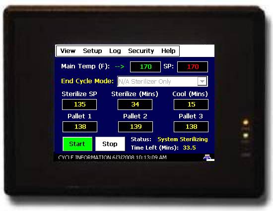
Pallet Heat-Treat (Sterilize cycle) Auto Printout at end of cycle printout

The Pallet Heat-Treat operation (whether configured as Pallet Heat-Treat only or Combination Kiln & Pallet Heat-Treat) dependent upon its' configuration will allow system to Auto print at end of Sterilization cycle - sample above showing data saved every minute. Regardless the Historical data file specific to a cycle can be viewed at any time and utilizing either File Utilities or with a LAN transferred to an FTP Server via Ethernet.
Alarm File - below is a Sample Alarm File - Kiln Alarm Description would show actual Alarm Description as named and configured by the OEM

Audit Trail - below is a sample audit trail

Averages Report is derived from a Historical File which can be plotted in graph form or with Averages as shown below. The Kiln Input Description would show actual Input Description as named and configured by the OEM

Return to: Main Kiln FDC-2010-K5C Page
Pallet Heat-Treat operational mode Pallet_Heat-Treat.htm
Kiln Information Links below:
Kiln mode: Primary Operator Display Views.htm
Main Views, Monitor Probes, Set Manual Outputs, Trending, Alarm Monitor & History and Audit Trail
Pallet Heat-Treat operational mode - see Pallet_Heat-Treat.htm
Kiln mode: Main Schedule Views.htm
Drying Schedule View, Schedule Edit/Run, Schedule Run, Hold, Stop; Drying Schedule View, Schedule Entry, Plot Schedule, Edit Schedules, Run Schedule, Advance to Next or Previous Stage and Add Subtract Time.
Kiln mode: Additional Temperature Monitor Sensors.htm
Optional temperature Monitor sensors; monitor only or used as additional Core Temperatures for Kiln Heat-Treat/Sterilize.
Kiln mode: Kiln EMC Operation.htm:
Description of EMC calculated values shown on Kiln's Main View and control logic if so configured.
Kiln mode: PC based KilnView Software Package.htm:
KilnView PC Software Review - communicate with up to 16 FDC-2010-K5C Controls as well as up to 48 single loop controls (applies to FDC-2010-K5C Kiln operational mode only; KilnView may not be used in the Pallet Heat-Treat operational mode).
Pallet Heat-Treat Sterilization Mode.htm
Review of Pallet Heat-Treat Sterilization mode; available configurations, control logic, operation, etc.
Links below offer descriptions common to both the Kiln & Pallet Heat-Treat operational modes and/or configuration
Data Logging & View Historical Data.htm:
System Data Logging Start: Kiln mode on start up, on Schedule Start or on Demand and in Pallet Heat-Treat mode on cycle start. History Data View and printing as graph or averages with High & Low values, etc. File Utilities to manually copy and/or delete Historical Data, Alarm, Audit and Schedule files and if connected to LAN, FTP Historical Data files to PC based FTP Server.
Description of LAN standard features: Remote Access (embedded VNC Server), email/SMS text on alarm, FTP of Historical Data files (embedded FTP client), Web page (embedded web page server) & Atomic Clock time/date update
Print Data Views, Historical Data files including Data Log files, Alarm files, Audit Trail files, Recipe files, etc.
System Security & Audit Trail.htm:
Multi level Security & Audit Trail Setup.
Import/Export Data Log, Schedule, Alarm & Audit directories from Compact Flash Card to I-Stick Memory via USB port.
User Configurable FDC-2010-K5C Settings: Decimal Point, Control Tuning, LAN settings, Input Offsets, Temperature Alarm Setpoints, Remote I/O Monitor, Degrees C/F, Setpoint Limits, Force System outputs allowing easy testing of all outputs without running control system, Kiln mode Fan Direction & Dwell Times, Kiln mode Schedule Recovery [Power Loss] and more.
OEM FDC-2010-K5C Control System Configuration as Kiln only, Pallet Heat-Treat only or Combination Kiln & Pallet Heat-Treat control system. Configure control outputs as relay on/off or analog output; Configure Linear Outputs as either Control or Retransmission of Dry & Web Bulb setpoints or temperatures; Names for Digital Inputs, Control & Alarm Outputs, Event Outputs; Configure up to 7 DI that can disable Control outputs and logic [schedule hold, heat enable, Fans, Spray Auto, etc.]; Configure additional Monitor / Core Temperature inputs
Information to schedule an on-line demonstration of the FDC-2010-K5C control system
Information on multi-language Help screens, Audio output and on-board tools to troubleshoot control system.
Review of features that if connected to 3rd party energy monitoring devices (Load Monitor / Shedding) to reduce energy costs by wiring digital inputs to start/stop/hold schedules and/or disable specific outputs until appropriate.
Panel Mount USB Adapter, standard and Nema 4X, providing front panel access to USB port for memory I-Stick and/or printing direct from the FDC-2010-K5C interface.
Dimensional Drawings, mechanical specifications and sample wiring diagrams.
FDC-2010-K5C Contact Techncial Support and Touch Screen Software Updates.htm
Contact information & links to download touch screen software updates.