


FDC-2010-K5C:Kiln Mode Schedule Views

click on display for larger graphic
FDC-2010-K5C (Main View) Runtime Menus:


![]()
![]()
The FDC-2010-K5C runtime menu system provides a familiar, easy to use interface while reducing screen “clutter” by eliminating extra buttons required for navigation. Each series of interface screens will have their own series of menus specifically focused on the tasks for the specific screen.
Shown above are the “top” level menus when the FDC-2010-K5C runtime first loads. A Help menu exist for every screen but is not shown in the menu items above. Note: The View above is for a combination Kiln & Pallet Heat-Treat configuration. If Pallet or Kiln only the View would have fewer choices; i.e. Kiln only would not have "Pallet View". This section on Schedules would not apply to a Pallet Heat-Treat only configuration.
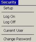
Schedule Menu: The Schedule menu provides access to schedule actions, edit and runtime views. From these screens a user can open, save, edit or delete as well as download schedules to the FDC-2010-K5C series controller. The Run, Hold and Stop drying schedule menu items will allow quick access to these functions if a schedule is already downloaded to the FDC-2010-K5C controller.
The remaining Menu items, View/Main View, Schedule, Setup, Log & Security are described in their own sections.
The Schedule Views Menu Prompts


The “Schedules” menu from FDC-2010-K5C main menu structure provides access to the automated schedule section of the FDC-2010-K5C. Select “Edit/Run” to enter the schedule entry section of the software. The Run, Hold and Stop drying schedule menu items at the main kiln view screen allows quick access to these functions if a schedule is already downloaded to the FDC-2010-K5C controller.
The Schedule “Views” menu provide the following functions:
Main View: Returns user to Main Kiln view.
Drying Schedule View: Display schedule view screen.
Drying Schedule Entry: Display schedule entry screen.
Plot Drying Schedule: Display schedule plot.
The schedule “Edit” menu provides the following functions:
New Drying Schedule: Clear all entries for new schedule generation.
Insert Stage: Insert a stage to current schedule.
Delete Stage: Delete the current stage from schedule.
Copy Stage: Copy current stage data.
Paste Stage: Paste current stage data.
Open Drying Schedule: Open drying schedule from compact flash.
Save Drying Schedule: Save drying schedule to compact flash.
Save Drying Schedule As: Save drying schedule as different name.
Delete Drying Schedule: Delete current drying schedule.
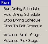
The schedule “Run” menu provides the following functions:
Run Drying Schedule: Start currently loaded drying schedule.
Hold Drying Schedule: Hold drying schedule that is running.
Stop Drying Schedule: Stop drying schedule that is running.
Advance Next Stage: Advance to next stage in currently running schedule.
Advance Prev Stage: Advance to previous stage in currently running schedule.

The drying schedule view provides the operator with all current data related to the drying schedule that is currently running. This is a view only screen and does not allow the operator to change parameters to the schedule that is running (setpoints, time etc .).
To change parameters for the currently running schedule , press the “views” menu and return to the main kiln screen. The schedule run info screen also displays the current schedule running as well as the schedule loaded into the controller.
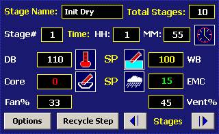
The schedule entry screen allows the user to enter, open and save schedules. Hundreds of schedules can be stored. Each schedule allows up to 99 stages.
The “Edit” menu provides copy, paste, insert and delete functions to simplify schedule entry.
Press the desired field to enter schedule data for dry bulb, wet bulb, core and EMC set points (if so configured) for each stage. Core, EMC, vent and fan speed setpoint fields will only be displayed if the kiln is equipped with these hardware options.
If relay operation is configured for fans and vents, settings for these options are available under the “Options” section for each stage.
Pressing the “Options” button provides the operator with all control output and /or event selections for each stage of the schedule.
Pressing the "Recycle Step" button allows the user to jump between different stages with in the Schedules - see Recycle Step section below.
Monitor Probe Control Logic option (if so configured by the OEM) will have a "core" setpoint field available on every stage.
When a “core” sensor & any additional “monitor” temperature inputs are configured within a system, and a “core” setpoint value is entered, a Stage Advance will occur when the “Core” and configured monitor sensors achieve the Core setpoint. Note: the monitor sensors to be included in the control logic are user selectable per stage.)
The Stage Advance logic is selectable on achieving Core setpoint; on a temperature rise or cool down to Core Setpoint.
An automatic Stage Advance on Temperature Rise is useful during “sterilization” processes that require all temperature probes be above a specific temperature before sterilization “time down” is allowed to begin/continue.
When the "Cool Down" stage option is selected the schedule will automatically advance to the next "stage" when all probes (probes activated per stage are user selectable) are <= the "core" setpoint programmed for the stage. This is useful during processes that require that all temperature probes be below a specific temperature before the schedule automatically continues to the next stage.
EMC (Equilibrium Moisture Content) is a calculated value (as is %RH) from the current Wet & active Dry bulb temperature values.
When so configured an EMC setpoint may be entered and selected to be active within each stage of a Schedule; the EMC selection box to enable EMC setpoint is entered in the schedule’s stage option screen. With EMC active for a specific stage, EMC control logic (global setting) allows either a Stage alarm output or Advance to the next stage once EMC setpoint is achieved (falling below setpoint).
Options button brings up the first of two screens showing available event & output functions for each stage.
Stage options allow the user to select which options (control/event outputs) are required for each stage of the schedule. The built in intelligence on the FDC-2010-K5C will automatically select or deselect options that are not allowed for certain kiln options. This reduces errors when entering a schedule and makes it easier for a new operator to get familiar with the FDC-2010-K5C system.
When the "Cool Down" stage option (shown on 2nd options page - not sample below) is selected and additional probes are configured for temperature probes with a "core" setpoint programmed into an automatic schedule, the schedule will automatically advance to the next "stage" when all probes (probes activated per stage are user selectable) are <= the "core" setpoint programmed for the stage. This is useful during processes that require that all temperature probes be below a specific temperature before the schedule automatically continues to the next stage. Probe usage combinations are selectable per stage when entering an automatic schedule.


Option Screen Notes:
DB Gar Soak and WB Gar Soak shown on sample Screen #2 refer to “Dry Bulb Guaranteed Soak” and “Wet Bulb Guaranteed Soak”; for more information refer to FDC-2010-K5C manual.
MON2 – MON6 shown on sample Screens #1 & #2 are shaded out. This is due to OEM configuration of the options. OEM Configuration may not only change the option names but also if they are active; MON4 – MON6 are not active. (MON = Monitor Temperature Sensor)
Guaranteed Soak:
Shown on above Options Screen: DB GAR Soak and WB GAR Soak
The Guaranteed Soak option allows the user to set a band for dry bulb and wet bulb. If during schedule run, the active dry bulb temperature or wet bulb temperature falls outside of this band, the schedule will hold until the active dry bulb temperature or wet bulb temperature is back within the band. The value entered for guaranteed soak is an "even sided" band above and below the current schedule setpoint for dry bulb and wet bulb. The guaranteed soak values are "global" and apply to all schedule stages.
The operation for guaranteed soak is enabled or disabled for dry bulb and wet bulb on a "per stage" basis by selecting or de-selecting the option (previous screen graphic) when configuring the stage options for each stage of the schedule.
Guaranteed Soak may be useful during “sterilization” processes that require specific Soak time when temperatures are above a specific temperature; any time the Dry or Wet bulbs are below the guaranteed soak limit the hold time would stop until the temperatures were within specified range of setpoint.
Configuration of the Guaranteed Soak Limits are set under the Views menu of Schedules - the section this web page reviews.

The stage recycle settings screen, accessed from the Main Schedule Entry screen "Recycle Step" button, allows the user to jump between different stages within the schedule. It can also be referred to as a "looping" function. This is useful for repeating the same sequence of stages over and over again without having to enter them into a schedule multiple times. It is valuable for providing the functionality to loop or repeat stages based on user schedule requirements.
Notes:
Stage Recycle Count: Number of times to jump
Recycle To Stage Number: Number of step to jump to once current stage is complete
The primary use for a recycle is to jump back to the beginning of a schedule and repeat the same steps over again for a predetermined number of times.
The schedule also has the ability to do nested looping. It has the ability to set up recycles on every stage throughout the schedule. It even has the ability to jump forward, skipping stages, only to allow them later by other recycle stage returning to the skipped steps. However, this can become confusing. Use caution with nested loops to prevent product loss. The schedule may not operate as expected due to multiple jump paths within the schedule.
Shown below is the screen that is shown when the "Recycle Step" button on the "Main Schedule Entry" screen is depressed.

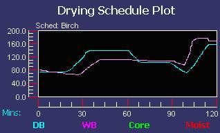
The schedule plot screen will trend the current schedule (schedule that is currently open or being edited). Both X and Y-axis values will auto-scale to the highest values for each axis. The time axis will plot the total time in minutes for the complete schedule.
OR

The schedule start screen allows the user to enter batch, operator and lot number as well as select the stage the schedule will start on; up to 10 characters may be used for each field - Batch, Operator & Lot#. The Batch, Operator and Lot# can be left empty if non-applicable and will not be included in the data file.
The delayed start fields allow an operator to delay to start of the schedule by entering “HH: MM” values; values may be set from 0-99 hours and from 0-59 minutes.
Press the “Start Schedule” button to start the schedule or the “Cancel” button to cancel schedule start.

The “Add/Subtract Time” view allows an operator to add or subtract time to an existing Stage within a running Schedule without changing the original schedule programmed into the system.
Adding Time - enter 0 to 99 hours and -2 to 59 minutes.
Subtract Time - system limits entry up to the time remaining in the current stage with maximum of -99 hours and -59 minutes for each field. Example: if 35 minutes left in current stage the system would not allow hour entry with an allowable range in minutes of -1 to -35 minutes.
This prompt is NOT found in the Schedule Menu system; Pressing the text to right of the “Stage” field on the Main Kiln view accesses this screen - see graphic below - Main View. Information on what is covered in the Main View - click: Primary Operator Display Views.htm
This dialog can only be accessed if a schedule is running and in hold. Enter the desired time by pressing the HH and MM fields and then press the “Done” button. Any time the add/remove time feature is used, a new ramp rate will be calculated (for dry bulb/wet bulb) for the new time entered.
Main Kiln View - Schedule Status

Shown above is the Main Kiln View. The "Stage: field is third line up from the bottom - see above on accessing Add/Subtract Time.
Options prompt: This prompt scrolls through the active outputs/events enabled for this Stage.
Return to: Main Kiln FDC-2010-K5C Page
Pallet Heat-Treat operational mode Pallet_Heat-Treat.htm
Kiln Information Links below:
Kiln mode: Primary Operator Display Views.htm
Main Views, Monitor Probes, Set Manual Outputs, Trending, Alarm Monitor & History and Audit Trail
Pallet Heat-Treat operational mode - see Pallet_Heat-Treat.htm
Kiln mode: Main Schedule Views.htm
Drying Schedule View, Schedule Edit/Run, Schedule Run, Hold, Stop; Drying Schedule View, Schedule Entry, Plot Schedule, Edit Schedules, Run Schedule, Advance to Next or Previous Stage and Add Subtract Time.
Kiln mode: Additional Temperature Monitor Sensors.htm
Optional temperature Monitor sensors; monitor only or used as additional Core Temperatures for Kiln Heat-Treat/Sterilize.
Kiln mode: Kiln EMC Operation.htm:
Description of EMC calculated values shown on Kiln's Main View and control logic if so configured.
Kiln mode: PC based KilnView Software Package.htm:
KilnView PC Software Review - communicate with up to 16 FDC-2010-K5C Controls as well as up to 48 single loop controls (applies to FDC-2010-K5C Kiln operational mode only; KilnView may not be used in the Pallet Heat-Treat operational mode).
Pallet Heat-Treat Sterilization Mode.htm
Review of Pallet Heat-Treat Sterilization mode; available configurations, control logic, operation, etc.
Links below offer descriptions common to both the Kiln & Pallet Heat-Treat operational modes and/or configuration
Data Logging & View Historical Data.htm:
System Data Logging Start: Kiln mode on start up, on Schedule Start or on Demand and in Pallet Heat-Treat mode on cycle start. History Data View and printing as graph or averages with High & Low values, etc. File Utilities to manually copy and/or delete Historical Data, Alarm, Audit and Schedule files and if connected to LAN, FTP Historical Data files to PC based FTP Server.
Description of LAN standard features: Remote Access (embedded VNC Server), email/SMS text on alarm, FTP of Historical Data files (embedded FTP client), Web page (embedded web page server) & Atomic Clock time/date update
Print Data Views, Historical Data files including Data Log files, Alarm files, Audit Trail files, Recipe files, etc.
System Security & Audit Trail.htm:
Multi level Security & Audit Trail Setup.
Import/Export Data Log, Schedule, Alarm & Audit directories from Compact Flash Card to I-Stick Memory via USB port.
User Configurable FDC-2010-K5C Settings: Decimal Point, Control Tuning, LAN settings, Input Offsets, Temperature Alarm Setpoints, Remote I/O Monitor, Degrees C/F, Setpoint Limits, Force System outputs allowing easy testing of all outputs without running control system, Kiln mode Fan Direction & Dwell Times, Kiln mode Schedule Recovery [Power Loss] and more.
OEM FDC-2010-K5C Control System Configuration as Kiln only, Pallet Heat-Treat only or Combination Kiln & Pallet Heat-Treat control system. Configure control outputs as relay on/off or analog output; Configure Linear Outputs as either Control or Retransmission of Dry & Web Bulb setpoints or temperatures; Names for Digital Inputs, Control & Alarm Outputs, Event Outputs; Configure up to 7 DI that can disable Control outputs and logic [schedule hold, heat enable, Fans, Spray Auto, etc.]; Configure additional Monitor / Core Temperature inputs
Information to schedule an on-line demonstration of the FDC-2010-K5C control system
Information on multi-language Help screens, Audio output and on-board tools to troubleshoot control system.
Review of features that if connected to 3rd party energy monitoring devices (Load Monitor / Shedding) to reduce energy costs by wiring digital inputs to start/stop/hold schedules and/or disable specific outputs until appropriate.
Panel Mount USB Adapter, standard and Nema 4X, providing front panel access to USB port for memory I-Stick and/or printing direct from the FDC-2010-K5C interface.
Dimensional Drawings, mechanical specifications and sample wiring diagrams.
FDC-2010-K5C Contact Techncial Support and Touch Screen Software Updates.htm
Contact information & links to download touch screen software updates.