


The Description below is for configuring VR Series directly from within the unit.
Configuration of a VR Series project file within Observer I or II PC software offers the same configuration screens, is quicker and easier to archive files. When using Observer software you must start with a Configuration file by first downloading a unit configuration, i.e. factory default settings directly to a CF card and then read same from a PC running Observer. Edit configuration and "save as" a new project file to the CF card and upload to the VR Series. For more information on Observer refer to VR Series Observer Software Review.htm
Press the Config key to enter the Configuration mode. The following buttons appear: Channel, Display, Tools, Instrument, Clock, System Info and Demo. Meanwhile, the following soft keys appear at the bottom: Save, Load, Default and Back.
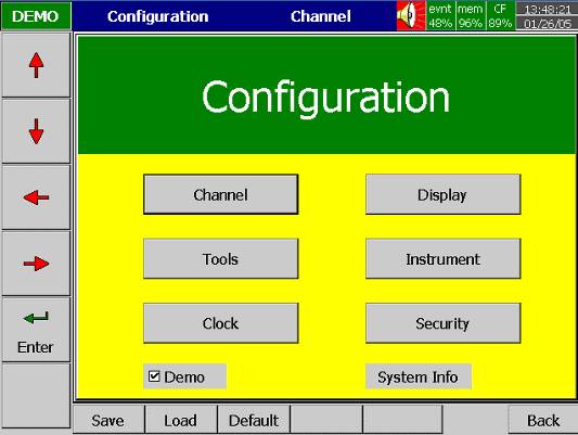
Enter: First select the mode by pressing directional keys ,¯,¬, ®, then press Enter key to enter any mode of Channel, Display, Tools, Instrument, Clock, System Info or Demo.
Save: Save configurations from recorder to storage media CF card.
To read the configuration and measured data from CF card on a PC for the first time or any time configuration has been changed, it is important to press Save key to save configuration changes to CF card beforehand.
Load: Load configuration from storage media CF card to recorder. (Recorder configuration can be saved to CF card either through Observer I / II software or downloaded to the CF card from another VR Series.)
Default: If the configuration is set incorrectly, Default is a useful key to recall the default settings on the analog input card inserted into rear expansion slot.
Back: Go back to the previous display.
Channel (Analog input, Digital input, Analog output, Math input)
Analog input
After entering the Configuration mode, select Channel and press the Enter key to get into Channel mode. It displays the Analog input AI first. Press directional keys <, > at the bottom to select the channel. Afterwards, press directional keys , ¯, ¬, ®, ¿ on the left hand side to select the column.
After Configuration 4.1 to 4.8, press Back key to return to real-time display, all configurations will be memorized.

Name: Define the name for each channel - maximum 6 characters. Press Enter, a keyboard and several keys appear. Desc: Description about a specific channel on the display.
Log Method: The method of logging measured data. Select the column, and then choose the Log method of Instant, Average, Minimum or Maximum data.
Disable: Select "Disable" when a specific channel is not required.
Instant: logging in the last measured data at the sampling interval
Average: logging in averaged measured data at the sampling interval
Minimum:Minimum: logging in minimum measured data at the sampling interval
Maximum: logging in maximum measured data at the sampling intervalLog Speed: It is the logging speed (recording speed) of measured data.Select the Log Speed column, then choose 1, 2, 5, 10, 30, 60 or 120 secondsOffset: It is offset value to correct the sensor error.
Gain: It is a multiplier to correct the sensor error.
Unit: The engineering unit of input
Range: Various input ranges can be set for voltage and current.Normally, it sets 0-1, 1-5, 0-5 or 0-10 V for the voltage, and set 0-20 or 4-20mA for the current.
Scale Unit: Defines the scale unit.
Scale Low: Defines the low scale with decimal if necessary. For instance, input 0-10 V, the Scale Low can be set up with value 0.00 to be correspondent to low range 0 V. Scale High: Defines the high scale with decimal if necessary.
For instance input 0-10 V, the Scale High can be set upwith value 100.00 to be correspondent to high range 10 V.
Refer to Event and Alarm Description for details configuration of same.
Press DI key to select the Digital input. Define the name, Description, and set up the Event accordingly. Press directional keys < > at the bottom to select the channel.
Analog output [optional]
Timer Function [standard]
Six Timer Functions are included as standard.
Select Tools, then press Enter key to get into Tools mode. Timer, Counter and Totalizer are defined here.
Counter and Totalizer are available only if the optional Math module was ordered.
Refer to the instruction manual and/or to for an overview refer to VR Series Special Features: Math, Totalize, etc.htm
Math Functions [optional]
Select Tools, then press Enter key to get into Tools mode. Timer, Counter and Totalizer are defined here.
Counter and Totalizer are available only if the optional Math module was ordered.
Refer to the instruction manual and/or to for an overview refer to VR Series Special Features: Math, Totalize, etc.htm
Press the Back key to return to the beginning of the Configuration mode. Select Display and press Enter key to get into Display mode. Display may have a maximum 6 Pages and each Page may display maximum 6 channels.

Mode: Defines the method of displaying data. Options are: Mix, Trend, Bar or Digital modes.
Direction: Selects the trend direction horizontal or vertical.
Background: Defines the background color of Trend mode in black or white
Pen: Defines a specific channel as a drawing pen, its color, width, DisplayHi and DisplayLo.
Channel: Selects a specific analog input AI or Mathematics Math, or selects Disable if a specific channel is not required.
Color: Selects the color for each pen.
Width: Selects the width of trend, 1-thin, 2-medium, 3-wide.
Low: Defines the low scale for a pen on the display.
High: Defines the high scale for a pen on the display.
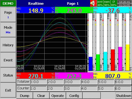
StatusBar: For users convenience when viewing the status of Totalizer, Counter, DI or DO, the user may enable these items in the StatusBar.
For example, after enable Totalizer 1 - 6 and Counter 1 - 6, two extra bars of Totalizers and Counters will appear at the lower part of display.
Math Functions; Counter, Timer & Totalizer
Optional Math functions provides 18 Derived Channels
Refer to the instruction manual and/or to for an overview refer to VR Series Special Features: Math, Totalize, etc.htm
Press Back key, to return to the beginning of Configuration mode.
Select Instrument then press Enter key to get into Instrument mode.
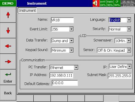
Name: Assigns a name for the recorder in maximum 8 characters.
Language: English, Spanish, French, German, Italian, Polish, Russian, Japanese, Korean, Thai, Chinese (simplified) and Chinese (traditional) may be selected.
Event Limit: Selects the highest possible numbers 256, 512 or 1024 for events (including alarms).
Security: Select "Normal" or "CFR-21" security.
· "Normal" security allows different users to key in a common password.
The CFR-21 offers Higher Security with 21 CFR part 11 type Features
§ Define each user as Supervisor or Operator with different authority to access the recorder and different passwords.
§ Audit trail function to record the user, time and what operator actions.
§ Details explained in manual 4.6 Security & CFR-21 part 11 Features.
Data Transfer:
Select Dump and Clear if the user wishes to clear the data on recorder after dumping data to PC or CF card.
Select Transfer and Remain if the user wishes to have the data remain on recorder after transferring data to PC or CF card. This allows user to view data in the History View that has been dumped to CF card or transferred via Ethernet with Observer II software.
Keypad Sound: Selects the following four options: disable, minimum, medium or maximum
LCD:
Screensaver: To prolong the life of the LCD display, it is suggested the display turn-off time is set to 1, 10, 20, 30, 40, 50 or 60 minutes after the recorder is operated. The recorder continues to record data while it is in the Screensaver mode. The display turns on again by pressing any soft key. When an alarm occurs, it turns on the display as well. The factory default setting for the Screensaver is 10 minutes.
Sensor:
Off & On: Keypad; Turn off & on by keypad. If the Screensaver is set 10 minutes, the display turns off 10 minutes after hands off from the recorder, and it turns on again after the user presses the keypad.
Off & On: IR; Turn off & on by infrared sensor. If it is the same Screensaver setting, the display turns off 10 minutes after the user is away from the recorder and it turns on when the user approaches the recorder within 2 meters.
Off: IR, On: Keypad; Turn off by infrared sensor, and turn on by keypad. If it is the same Screensaver setting, the display turns off 10 minutes after the user is away from the recorder and it turns on again after the user presses the keypad.
Communications
PCTransfer:
Selects RS-232/RS-485/RS-422, or standard Ethernet communication.
RS-232, RS-485, RS-422:
or 115200.
IP:
Select Automation if the server on the network automatically allocates the IP address for the recorder.
Select User Define to manually set a fixed address for the recorder. Two new columns will appear for keying in fixed addresses.
IP Address: Defines the correct address of the recorder on the network
Subnet Mask: Defines the correct SubnetMask address on the network
Default Gateway: Different Gateway has different IP address on Ethernet.
Press Back key, to return to the beginning of Configuration mode.
Selects Clock then presses the Enter key to get into Clock (Date/Time) mode to set up the local time.
Date Style: Selects either month/date/year or date/month/year
Date/Time: Set up the local time. Use directional keys going to the Apply column, and then press the Enter Key to apply it to the recorder.
Summer time / Daylight Savings: Summer time / Daylight Savings may be enabled and set to occur at specific dates.
Normal & CFR-21 High Security with CFR-21 part 11 Type Features
In instruction manual 4.4 Instrument, select "Normal" Security or "CFR-21" High Security

"Normal" Security: With “Normal” security selected in “4.4 Instrument” the Security Level dropdown allows “None” or “Security”. With “None” there is no password; with “Security” a common password for all users is used; password maximum is 8 characters. Once the password has been created the user needs to enter the password whenever Config, Dump, Clear or Operate soft keys are required. These keys enable the user to do configuration, dump data, clear data or manually operate the job.
"CFR-21" Security Features: When the “CFR-21” is selected in “4.4 Instrument” the recorder operates under more restricted rules, many of which are required by CFR-21 Part 11. The CFR-21 security selection defines two types of users, Supervisor and Operator, each with different authority to access the recorder by using different passwords as shown in the graphic above.
Note: The VR Series, as a component, has NOT been validated to comply with FDA CFR-21 Part 11. Typically the complete process made up of numerous components, software & procedures are validated as a system, not as individual components. It is the end user’s responsibility to validate the VR Series and/or other components & processes in the system are in compliance with appropriate CFR-21 part 11 regulations.
Time limit during operation: If 10 minutes or longer since the last operator key action requires the user to enter password again.
Audit Trail: CFR-21 Security offers audit trail function to record the user, time and operator actions to the event list. Incorrect password and unauthorized operation will be recorded into the event list as well.CFR-21 Security Operator Levels:
Supervisor: Supervisor can define all the user names including other Supervisors and Operators with a maximum of 30 users. Supervisor has access to all recorder functions. At least one Supervisor with an unlimited Time of Validity must be active.
Operator: Access to vertical keys to view the historical data, events and status, but no authority to access horizontal keys to do configuration, dump or clear data.
CFR-21 Security Password Time of Validity:
The Password Time of Validity may be configured as “Unlimited Time” or as 30, 60 or 90 days. If specified as 30, 60 or 90 days the account will be closed after the specified number of days; however the system will request the user to key in a new or remain with the original password when the user attempts to log in.
VR Series Security; CFR21 Part 11 Features.htm
The Demo mode is a simulation mode used as a sales tool for demonstration purposes.
It was set to simulate 18 AI analog inputs, 12 Math, 6 DI digital inputs and 6 DO digital outputs.
To start the automatic demonstration, first enable Demo mode, then turn the power off and on to make it effective.
To stop the automatic demonstration and return to real mode with real inputs, first disable Demo mode, then turn
the power off and on.
The system information includes System version, memory, CF card, Ethernet IP address and Slots status.
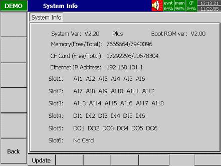
System Ver: It is the firmware version of the recorder. V2.20 means the present firmware version of recorder. Plus means with the option of Math, Counter, Totalizer & CFR-21 features.
Boot ROM ver: It is version of Boot ROM.
Memory (Free / Total): Indicates the percentage of free memory to total memory reserved on the recorder. 8 MB memory on board is reserved for storing measured data. A small icon on the top right indicates the percentage of free memory e.g.: mem 96%.
CF Card (Free / Total): Indicates the percentage of free memory to total memory of the Compact Flash card. e.g. CF 84%.
Ethernet IP Address: It is the present IP address of the recorder.
Slot 1 though 6: Indicates the status of all Slots and the cards been inserted in. The cards include Analog Input AI, Digital Input DI and Digital Output DO (6 relay card).
Update: The Update key is located at left lower side. It is the key to upgrade new firmware. After the new firmware is downloaded from a PC to the CF card insert the CF card in the VR Series CF slot. Then press this key to upgrade it. It may take a few seconds to finish the process.
VR18_Brochure_v2.37_January-2021.pdf
VR18_Manual_V2.37_November-2011.pdf
VR06_Brochure_v2.37_January-2021.pdf
VR06_Manual_V2.37_November-2011.pdf
VR Series_NEMA_4_Brochure_Feb-2007.pdf
VR06-18 Guidelines 21CFR part 11.pdf
VR06-18: Series FAQ's.pdf [40KB]
VR06-18: Series 2-Year Warranty Statement.pdf [13KB]
VR06-18: Firmware Update Sheet.pdf
VR06-18: CF Card Memory Calculations.zip
VR06-18: Reset to Factory Default
Return To:
VR06-18: Recorder Home Page.htm
VR06-18: Sample Screen Display & Operational Review.htm
VR06-18: Event & Alarm Description.htm
VR06-18: Installation: Panel or Bench Top Mounting.htm
VR06-18: Special Features: Math, Totalize, etc.htm
VR06-18: Observer Software Review.htm
VR06-18: Technical Support Documentation.htm
VR06-18: Download Firmware and Observer Software.htm
VR06-18: Security; CFR21 Part 11 Features.htm